The Bananaquits
Introduction
System design is the process of defining the elements of a system such as the architecture, modules and components, the different interfaces of those components and the data that goes through that system.
With the held of system modeling we want to precise the definition of system functionality and show what has to be realized, but without predefining how it will be realized.
You can say the implementation stage of software development is the process of converting a
system specification into an executable system. It always involves processes of software/System
design and programming but, also involve the refinement of the software specification.
To achieve the system specification we will use Object-Oriented-System-Modeling-Methods.
The following diagrams helped us to gain different views and level of details.

(by Avanthi)
Describes how objects collaborate with each other with some behavior.
Interaction diagrams depict
*System’s dynamic behavior.
*Describes system’s message flow.
*Describes interaction between the objects.
*Object’s structural organization.
UML comes with two types of interaction diagrams
*Sequence diagram.
*Class diagram.
(by Pooja)
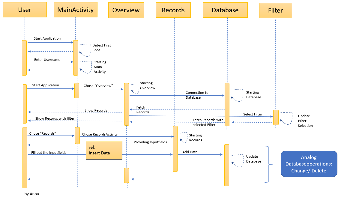
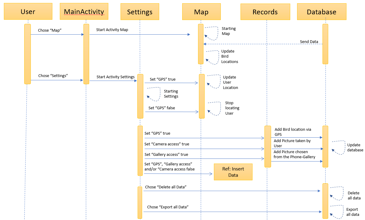
The Sequence diagram is an Interaction diagram that shows how objects operate with one another and in what order.It is a construct of a message sequence chart. A sequence diagram shows object interactions arranged in time sequence. Here, the horizontal axis represents the involved interaction partners such as lifelines and the vetical axis shows the chronological order of the interactions.
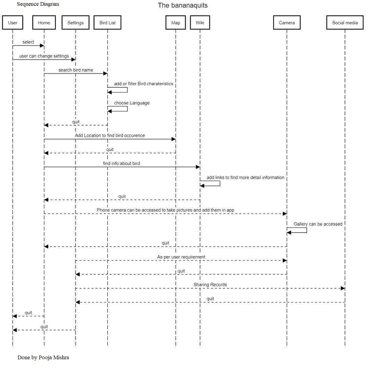
(by Anna & Vivi)
Class diagrams are one of the most useful types of diagrams in UML as they clearly map out the structure of a particular system by modeling its classes, attributes, operations, and relationships between objects. It represents the static view of an application.
UML (Unified Modelling Language) was set up as a standardized model to describe an object-oriented programming approach.
Keyfacts
→ A class diagram models the static structure of a system.
→ shows relationships between classes, objects, attributes, and operations.
Notation:
Classes represent an abstraction of entities with common characteristics.
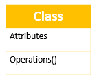
The class shape itself consists of a rectangle with three rows. The top row contains the name of the class, the middle row contains the attributes of the class, and the bottom section expresses the methods or operations that the class may use.They are services the class provides.
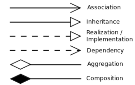
Associations: Associations represent static relationships between classes.
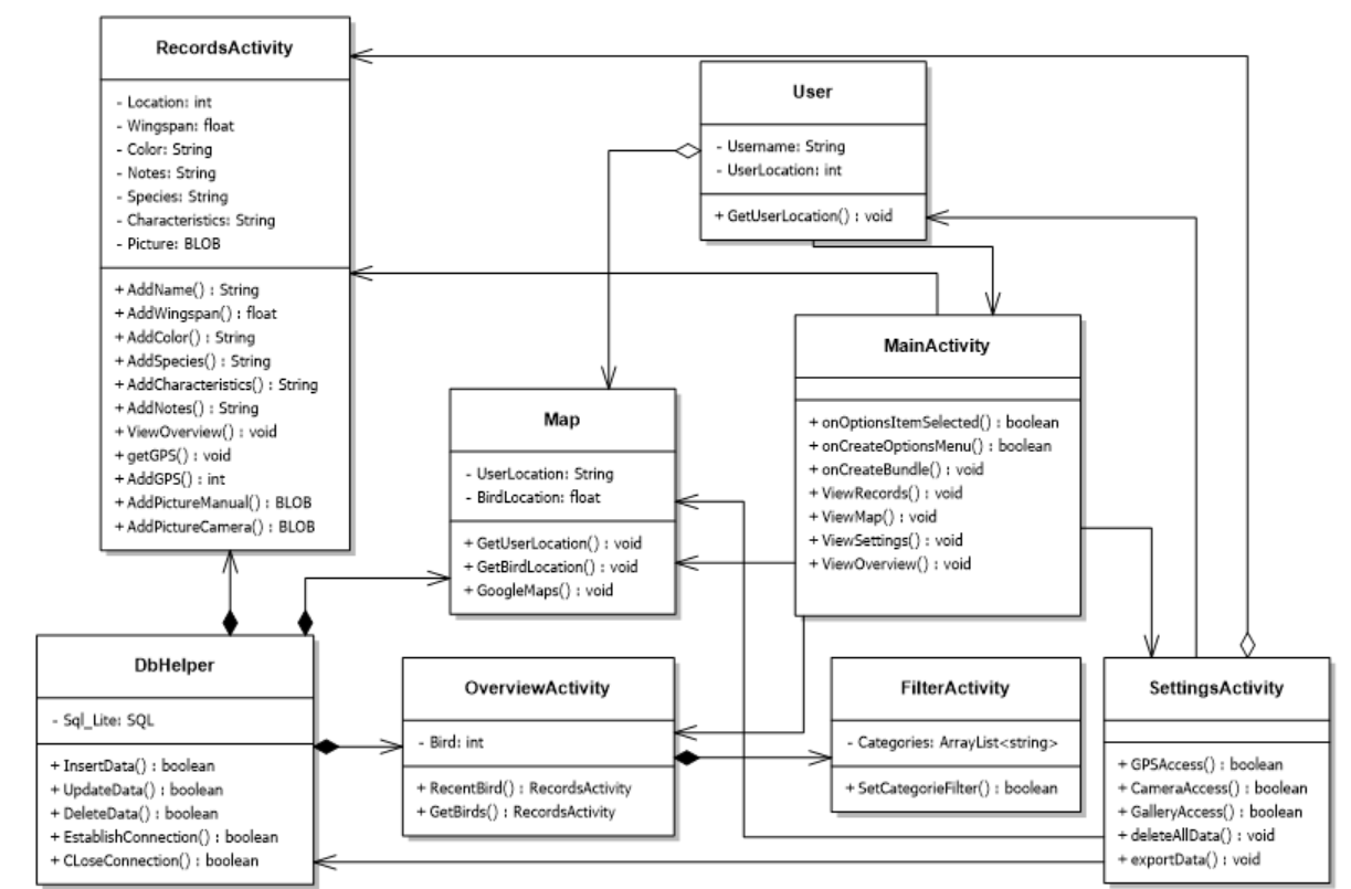
Our Class Diagram
In total 8 classes:
→ every Activity/Page is represented by one class
→ Subclasses (Filter)
→ Database Class to store the records
The methods shown in the class Diagrams represent the required functions.
(Functional and nondfunctional Requirements)
In the following i’m going to explain the structure partly. Self-explanatory elements (InsertData, AddName etc) will not be discussed.
MainActivity:
Homepage
The MainActivity is the start page of the application and is always displayed to the users at the beginning.
The Users have the ability to navigate to the other Activitys/Pages/Views.
→ Records,Map, Settings and Overview
Methods
onCreate() Bundle ⇒ Initialize the MainActivity.
onCreateOptionsMenu() Bundle ⇒ Initialize the Menu Items.
onOptionsItemSelected() Bundle ⇒ Is calles whenever an item in options menu is selected.
OverviewActivity:
The user has the possibility to get an overview of all already recorded birds.
Methods
GetBirds() ⇒ shows all recorded birds in a list.
RecentBird() ⇒ shows the last edited records.
RecordsActivity:
Provides the Inputfields for the documentation.
Methods
ViewOverview() ⇒ The user can navigate to the OverviewActivity.
GetGPS() ⇒ In case the user has allowed GPS-Access in the settings, the GPS data will be used (Analog Camera).
AddGPS() ⇒ The user can add the GPS-Data manually (Analog Camera).
FilterActivity:
Subclass of Overview ⇒ (Composition Relationship)
Provides the possibility to sort and filter the Records.
Attribute: Categories
→ Variable to hold the categories selected by the user.
Methods
SetCategoryFilter() ⇒ Set the filter selected by the user.
Maps:
The user can get the Userlocation & the Birdlocation.
The Use of GPS depends on the Settings in the SettingsActivity.
Methods
Googlemaps() ⇒ open googlemaps in the browser with the selected location.
DbHelper:
Controller of our application.
It is handling all communication with database and generate appropriate data required by the Views(Activities).
Attributes
sql_lite ⇒ Handle for SQL Lite database.
SeetingsActivity:
The user can give the app access permissions for the camery, gallery and GPS.
Changes in the Sequence Diagram
After we started with the programming, some changes had to be made to the diagram. In the following you can see our first sketch.
No.2
Quick reminder:
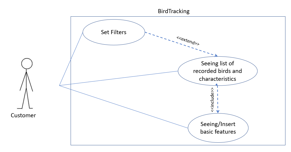
Here you can see the matching part of the Use Case Diagram.
(Article No.2 Requirements Analysis)

(by Vivi)
Design patterns are used to solve a specific software design problem. They describe the essential design decisions like class and object arrangements and serve as a kind of recipe, wich help to solve a programming task. By using Design Pattern, a System-Design becomes flexible, reusable, expandable, easier to use, and stable to change.
For our purpose we chose the Model-View-Control Pattern (short: MVC). With the MVC it’s possible to develope apps by keeping the data wich is used in the program, and the visual component of the program separate from one another. These two components interacting only with a controller containing the logic of the program. Because of that the view and the model interact only with the controller and NEVER with each other.
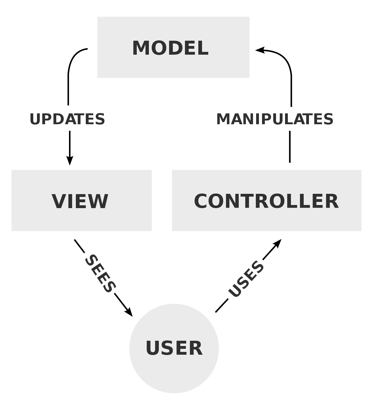
Source:
<a href= https://en.m.wikipedia.org/wiki/Model–view–controller> https://en.m.wikipedia.org/wiki/Model–view–controller</a>
Accordenly the MVC consist of three classes: Model, View and Control. The Model-Class (in our case: Records) represents an object wich is carrying data. The View-Class (in our case: Overiew) represents the visualization of the data that the Model-Class contains. The Controller-Class (in our case: DBHelper) controls the data flow into the Model-Class and updates the View whenever data changes.

(by Anna)
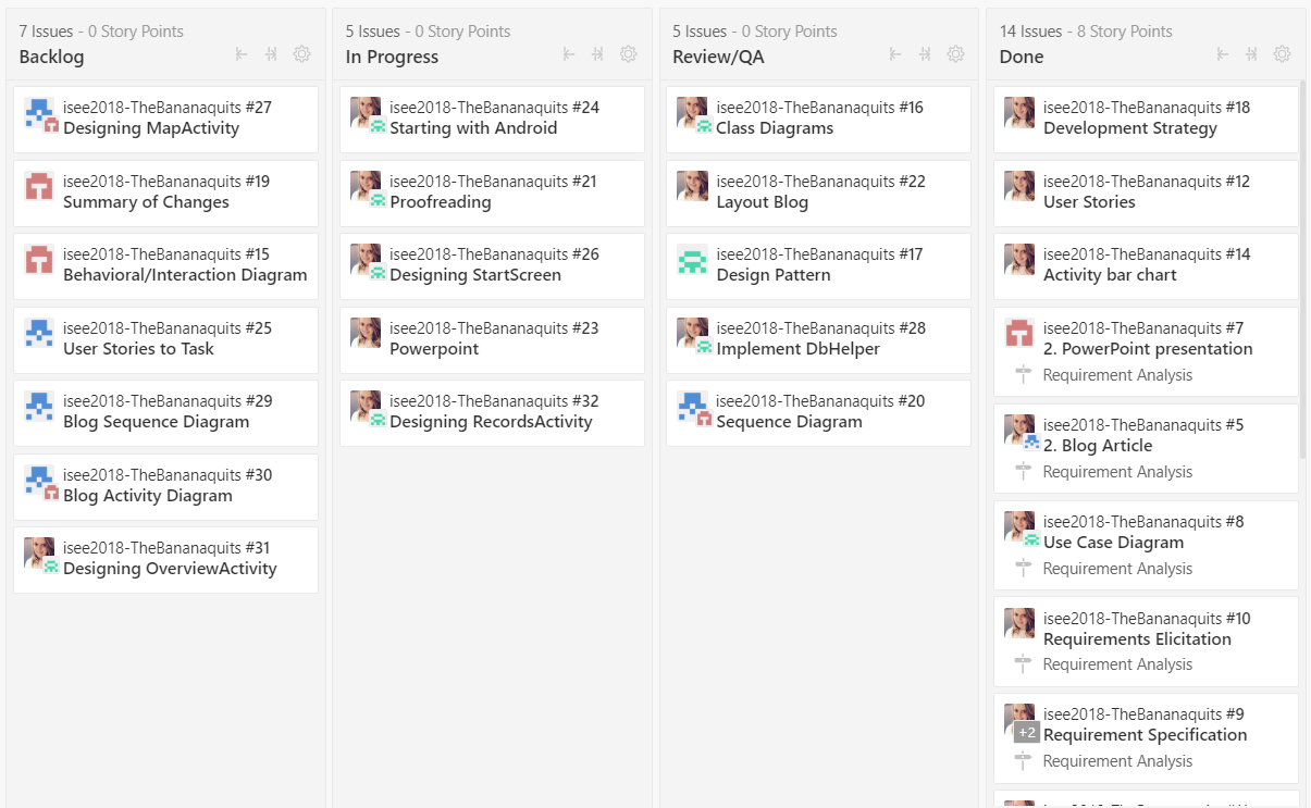
To keep a Track of all the work we use the Zenhub Dashboard.
The Dashboard provides a quick and simple overview about the Backlog, Work in Progress and Issues which are in Review.
We have also decided to include blogging as well as presentation and issues so that we have an idea on who is doing what.
• All user stories are going to be broken down into several Epics and logged in Backlog.
• Regulary Sprintplanning.
• Assigned tasks are analysed and difficulties are discussed in short meetings.
• Sprint review & discussions are done via facebook.

(Avanthi)
We have divided our work into four parts as interactions diagrams, sequential diagrams, design pattern and class diagrams.We did our part according to that.
Anna,Avanthi,Pooja,Viviane
Layout & Design by Anna


